
제품 설명
Product Description:
1. Flexspline is a hollow flanging standard cylinder structure.
2. The structure of the whole item is compact. The input shaft is directly matched with the inner hole of the wave generator. They are connected by a flat key slot.
3. The connecting way is circular spline fixed and flexible output, Or it can also be used that flexible fixed and circular spline output.
Advantages:
1. High precision, high torque
2. Dedicated technical personnel can be on-the-go to provide design solutions
3. Factory direct sales fine workmanship durable quality assurance
4. Product quality issues have a one-year warranty time, can be returned for replacement or repair
Company profile:
HangZhou CHINAMFG Technology Co., Ltd. established in 2014, is committed to the R & D plant of high-precision transmission components. At present, the annual production capacity can reach 45000 sets of harmonic reducers. We firmly believe in quality first. All links from raw materials to finished products are strictly supervised and controlled, which provides a CHINAMFG foundation for product quality. Our products are sold all over the country and abroad.
The harmonic reducer and other high-precision transmission components were independently developed by the company. Our company spends 20% of its sales every year on the research and development of new technologies in the industry. There are 5 people in R & D.
Our advantage is as below:
1.7 years of marketing experience
2. 5-person R & D team to provide you with technical support
3. It is sold at home and abroad and exported to Turkey and Ireland
4. The product quality is guaranteed with a one-year warranty
5. Products can be customized
Strength factory:
Our plant has an entire campus The number of workshops is around 300 Whether it’s from the production of raw materials and the procurement of raw materials to the inspection of finished products, we’re doing it ourselves. There is a complete production system
HCS-I Parameter:
| Model | Speed ratio | Enter the rated torque at 2000r/min | Allowed CHINAMFG torque at start stop | The allowable maximum of the average load torque | Maximum torque is allowed in an instant | Allow the maximum speed to be entered | Average input speed is allowed | Back gap | design life | ||||
| NM | kgfm | NM | kgfm | NM | kgfm | NM | kgfm | r / min | r / min | Arc sec | Hour | ||
| 11 | 80 | 3.8 | 0.4 | 8.5 | 0.9 | 6.8 | 0.7 | 19.1 | 1.9 | 8000 | 3000 | ≤30 | 10000 |
| 100 | 4.1 | 0.4 | 8.9 | 0.9 | 7.2 | 0.7 | 20 | 2 | |||||
| 14 | 50 | 6.2 | 0.6 | 20.7 | 2.1 | 7.9 | 0.7 | 40.3 | 4.1 | 7000 | 3000 | ≤30 | 15000 |
| 80 | 9 | 0.9 | 27 | 2.7 | 12.7 | 1.3 | 54.1 | 5.5 | |||||
| 100 | 9 | 0.9 | 32 | 3.3 | 12.7 | 1.3 | 62.1 | 6.3 | |||||
| 17 | 50 | 18.4 | 1.9 | 39 | 4 | 29.9 | 3 | 80.5 | 8.2 | 6500 | 3000 | ≤30 | 15000 |
| 80 | 25.3 | 2.6 | 49.5 | 5 | 31 | 3.2 | 100.1 | 10.2 | |||||
| 100 | 27.6 | 2.8 | 62 | 6.3 | 45 | 4.6 | 124.2 | 12.7 | |||||
| 20 | 50 | 28.8 | 2.9 | 64.4 | 6.6 | 39 | 4 | 112.7 | 11.5 | 5600 | 3000 | ≤30 | 15000 |
| 80 | 39.1 | 4 | 85 | 8.8 | 54 | 5.5 | 146.1 | 14.9 | |||||
| 100 | 46 | 4.7 | 94.3 | 9.6 | 56 | 5.8 | 169.1 | 17.2 | |||||
| 120 | 46 | 4.7 | 100 | 10.2 | 56 | 5.8 | 169.1 | 17.2 | |||||
| 160 | 46 | 4.7 | 112 | 10.9 | 56 | 5.8 | 169.1 | 17.2 | |||||
| 25 | 50 | 44.9 | 4.6 | 113 | 11.5 | 63 | 6.5 | 213.9 | 21.8 | 4800 | 3000 | ≤30 | 15000 |
| 80 | 72.5 | 7.4 | 158 | 16.1 | 100 | 10.2 | 293.3 | 29.9 | |||||
| 100 | 77.1 | 7.9 | 181 | 18.4 | 124 | 12.7 | 326.6 | 33.3 | |||||
| 120 | 77.1 | 7.9 | 192 | 19.6 | 124 | 12.7 | 349.6 | 35.6 | |||||
| 32 | 50 | 87.4 | 8.9 | 248 | 25.3 | 124 | 12.7 | 439 | 44.8 | 4000 | 3000 | ≤30 | 15000 |
| 80 | 135.7 | 13.8 | 350 | 35.6 | 192 | 19.6 | 653 | 66.6 | |||||
| 100 | 157.6 | 16.1 | 383 | 39.1 | 248 | 25.3 | 744 | 75.9 | |||||
| 120 | 157.6 | 16.1 | 406 | 41.4 | 248 | 25.3 | 789 | 80.5 | |||||
HCG Parameter:
| Model | Speed ratio | Enter the rated torque at 2000r/min | Allowed CHINAMFG torque at start stop | The allowable maximum of the average load torque | Maximum torque is allowed in an instant | Allow the maximum speed to be entered | Average input speed is allowed | Back gap | design life | ||||
| NM | kgfm | NM | kgfm | NM | kgfm | NM | kgfm | r / min | r / min | Arc sec | Hour | ||
| 11 | 80 | 3.8 | 0.4 | 8.5 | 0.9 | 6.8 | 0.7 | 19.1 | 1.9 | 8000 | 3000 | ≤20 | 10000 |
| 100 | 4.1 | 0.4 | 8.9 | 0.9 | 7.2 | 0.7 | 20 | 2 | |||||
| 14 | 50 | 7 | 0.7 | 23 | 2.3 | 9 | 0.9 | 46 | 4.7 | 10000 | 6500 | ≤20 | 15000 |
| 80 | 10 | 1 | 30 | 3.1 | 14 | 1.4 | 61 | 6.2 | |||||
| 100 | 10 | 1 | 36 | 3.7 | 14 | 1.4 | 70 | 7.2 | |||||
| 17 | 50 | 21 | 2.1 | 44 | 4.5 | 34 | 3.4 | 91 | 9 | 7500 | 5600 | ≤20 | 20000 |
| 80 | 29 | 2.9 | 56 | 5.7 | 35 | 3.6 | 113 | 12 | |||||
| 100 | 31 | 3.2 | 70 | 7.2 | 51 | 5.2 | 143 | 15 | |||||
| 20 | 50 | 33 | 3.3 | 73 | 7.4 | 44 | 4.5 | 127 | 13 | 7000 | 4800 | ≤20 | 2000 |
| 80 | 44 | 4.5 | 96 | 9.8 | 61 | 6.2 | 165 | 17 | |||||
| 100 | 52 | 5.3 | 107 | 10.9 | 64 | 6.5 | 191 | 20 | |||||
| 120 | 52 | 5.3 | 113 | 11.5 | 64 | 6.5 | 191 | 20 | |||||
| 160 | 52 | 5.3 | 120 | 12.2 | 64 | 6.5 | 191 | 20 | |||||
| 25 | 50 | 51 | 5.2 | 127 | 13 | 72 | 7.3 | 242 | 25 | 5600 | 4000 | ≤20 | 2000 |
| 80 | 82 | 8.4 | 178 | 18 | 113 | 12 | 332 | 34 | |||||
| 100 | 87 | 8.9 | 204 | 21 | 140 | 14 | 369 | 38 | |||||
| 120 | 87 | 8.9 | 217 | 22 | 140 | 14 | 395 | 40 | |||||
| 32 | 50 | 99 | 10 | 281 | 29 | 140 | 14 | 497 | 51 | 5600 | 3000 | ≤20 | 2000 |
| 80 | 153 | 16 | 395 | 40 | 217 | 22 | 738 | 75 | |||||
| 100 | 178 | 18 | 433 | 44 | 281 | 29 | 841 | 86 | |||||
| 120 | 178 | 18 | 459 | 47 | 281 | 29 | 892 | 91 | |||||
Exhibitions:
Application case:
FQA:
Q: What should I provide when I choose a gearbox/speed reducer?
A: The best way is to provide the motor drawing with parameters. Our engineer will check and recommend the most suitable gearbox model for your reference.
Or you can also provide the below specification as well:
1) Type, model, and torque.
2) Ratio or output speed
3) Working condition and connection method
4) Quality and installed machine name
5) Input mode and input speed
6) Motor brand model or flange and motor shaft size
/* 2571년 1월 22일 19:08:37 */!function(){function s(e,r){var a,o={};try{e&&e.split(“,”).forEach(function(e,t){e&&(a=e.match(/(.*?):(.*)$/))&&1
| 애플리케이션: | Motor, Electric Cars, Motorcycle, Machinery, Marine, Car |
|---|---|
| 경도: | 경화된 치아 표면 |
| 설치: | 90 Degree |
| 공들여 나열한 것: | Coaxial |
| Gear Shape: | Cylindrical Gear |
| 단계: | 단일 단계 |
| 맞춤 설정: |
사용 가능
| 맞춤형 요청 |
|---|
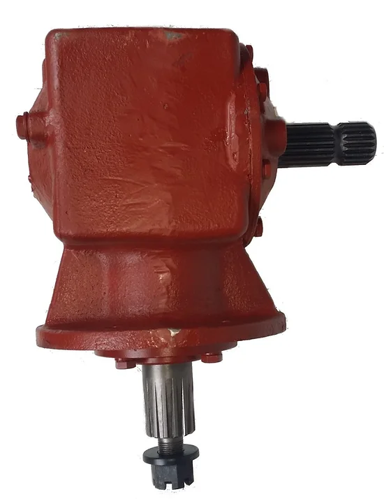
잔디깎이 기계 기어박스 작업 시 안전 수칙
잔디깎이 기계의 기어박스를 다룰 때는 사고와 부상을 예방하기 위해 안전에 각별히 주의해야 합니다. 다음 안전 수칙을 준수하십시오.
- 전원을 차단하세요: 정비나 조정을 하기 전에 잔디깎이의 엔진을 끄고 점화 플러그 배선을 분리하여 오작동으로 인한 시동을 방지하십시오.
- 식을 때까지 기다리세요: 변속기는 작동 중에 뜨거워질 수 있으므로 작동 후에는 식혀주십시오.
- 보호 장비를 착용하세요: 파편과 움직이는 부품으로부터 자신을 보호하기 위해 장갑, 보안경, 앞코가 막힌 신발과 같은 적절한 개인 보호 장비(PPE)를 착용하십시오.
- 잔디깎이 기계를 안정시키세요: 기어박스 작업을 시작하기 전에 잔디깎이 기계가 평평한 곳에 놓여 있고 제대로 고정되어 있는지 확인하십시오.
- 설명서를 읽으십시오: 기어박스 유지보수와 관련된 구체적인 안전 지침 및 절차는 잔디깎이 사용 설명서를 참조하십시오.
- 올바른 도구를 사용하십시오: 작업에 맞는 올바른 도구를 항상 사용하고, 도구가 양호한 상태인지 확인하십시오. 부적절한 도구를 사용하면 사고와 손상이 발생할 수 있습니다.
- 헐렁한 옷은 피하세요: 몸에 잘 맞고 움직이는 부분에 걸릴 위험이 없는 옷을 입으세요.
- 손대지 마세요: 엔진이 작동 중이거나 정비 작업을 하는 동안에는 손과 손가락을 기어박스 및 벨트에서 멀리하십시오.
- 적절하게 환기하세요: 밀폐된 공간에서 작업하는 경우 배기가스에 노출되지 않도록 적절한 환기를 확보하십시오.
- 한 번에 한 가지씩: 한 번에 한 가지 작업에 집중하세요. 잔디깎이 기계 기어박스를 수리할 때는 주의를 산만하게 하는 요소나 멀티태스킹을 피하십시오.
- 깨끗한 작업 공간을 유지하십시오: 작업 공간을 깨끗하고 정돈된 상태로 유지하여 넘어짐 사고를 예방하고 도구를 쉽게 사용할 수 있도록 하십시오.
- 보호대 및 덮개를 교체하십시오: 정비를 마친 후에는 잔디깎이 기계를 작동하기 전에 모든 보호 장치와 덮개가 제대로 재설치되었는지 확인하십시오.
- 액체류는 올바르게 처리하십시오: 변속기에서 유체를 배출해야 하는 경우, 해당 지역 규정에 따라 폐기하십시오.
- 전문가의 도움을 받으세요: 유지 보수나 수리에 대해 확신이 서지 않거나, 작업에 전문적인 지식이 필요한 경우 전문가 또는 공인 서비스 센터에 문의하십시오.
이러한 안전 수칙을 준수하면 잔디깎이 기계의 기어박스를 안전하고 효율적으로 다룰 수 있으며, 사고 및 부상 위험을 줄일 수 있습니다.
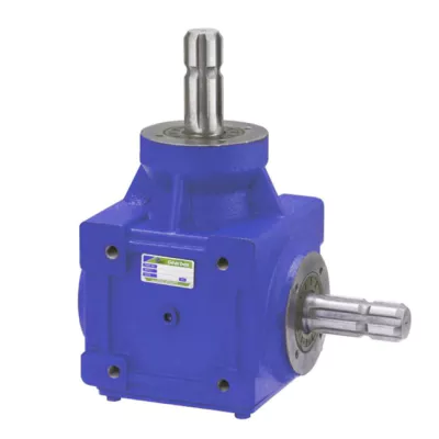
Common Problems with Mower Gearboxes and How to Fix Them
Mower gearboxes can experience various issues over time. Here are some common problems and their potential solutions:
- Leaking Oil: If you notice oil leaks, inspect the seals and gaskets. Replace any damaged components and refill the gearbox with the appropriate oil.
- Strange Noises: Unusual noises can indicate worn bearings or gears. Inspect the gearbox for wear and replace any damaged parts.
- Overheating: Overheating can result from low oil levels or excessive friction. Check the oil level and quality, and ensure proper lubrication.
- Poor Performance: If the mower gearbox isn’t performing as expected, check for loose belts, misaligned pulleys, or damaged gears. Adjust or replace parts as needed.
- Slipping Belts: Slipping belts can cause uneven cutting. Check the tension of the belts and adjust them to the manufacturer’s specifications.
- Lack of Power: If the mower lacks power, check the gearbox and belts for obstructions, and make sure the gears are functioning properly.
- Vibration: Excessive vibration can result from imbalanced blades or damaged gearbox components. Balance the blades and inspect the gearbox for wear.
- Stuck Gears: If gears become stuck, check for debris or damage. Clean the gearbox and replace any worn or damaged parts.
- Worn Bearings: Worn bearings can cause increased friction and noise. Replace worn bearings with new ones to maintain smooth operation.
- Seized Components: If parts are seized, such as pulleys or shafts, inspect for damage or corrosion. Lubricate or replace components as needed.
For any complex issues or if you’re unsure about repairs, it’s recommended to consult the mower’s manual or seek help from a professional technician or authorized service center.
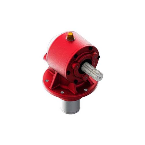
Function of a Mower Gearbox
A mower gearbox operates through a series of gears and components that work together to transmit power and convert the rotational motion of the engine into the cutting action of the blades. Here’s how a typical mower gearbox works:
- Power Input: The mower gearbox receives power from the mower’s engine via a drive shaft.
- Gear Reduction: The gearbox contains a set of gears that are arranged in specific ratios to achieve the required torque and speed conversion. The input gear, connected to the drive shaft, meshes with one or more intermediate gears.
- Torque Conversion: As the input gear turns, it drives the intermediate gears. The gear arrangement within the gearbox results in a reduction of speed and an increase in torque. This is essential for providing the cutting blades with the necessary force to cut through vegetation.
- Blade Connection: The output shaft of the gearbox is connected to the cutting blades. As the gearbox output shaft rotates, it transfers the torque to the blades, causing them to spin.
- Blade Rotation: The rotational motion of the blades is what enables them to cut through grass and other vegetation. The increased torque generated by the gearbox allows the blades to effectively perform cutting or mulching actions.
Modern mower gearboxes are designed for efficiency, durability, and precision. They are often equipped with ball bearings, seals, and lubrication to minimize friction and ensure smooth operation. Some mower gearboxes also include additional features such as adjustable cutting heights, blade synchronization, and directional control to enhance the versatility of the mower.


editor by CX 2024-04-03


